Class A Airspace
Class A airspace is not charted on visual navigation charts.
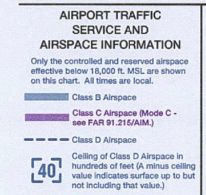
Class B Airspace
Each sector is depicted by heavy blue lines on sectional and terminal charts, along with that sector's floor and ceiling altitudes, which are shown with the last two digits omitted. Class B airspace is depicted in an abbreviated form on a world aeronautical chart.
Class C Airspace
Class C airspace is depicted on sectional and some terminal charts with the use of solid magenta lines, along with the floor and ceiling altitudes, which are shown with the last two digits omitted. World aeronautical charts show Class C airspace in an abbreviated form.
Typically, Class C airspace extends from the surface to 4,000 feet AGL out to 5 nautical miles from the primary airport. From 5 to 10 NM, the airspace typically extends from 1,200 feet AGL up to 4,000 feet AGL. Of course, each airspace is tailored, as necessary.
Class D Airspace
A dashed blue line shows the lateral limits of the Class D, while the ceiling altitude is shown with the last two digits omitted. Typical Class D airspace dimensions are surface to 2,500 feet AGL out to 4 NM from the primary airport.
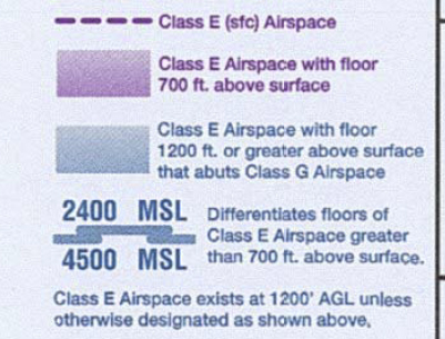
Class E Surface Areas
A dashed magenta line shows the lateral dimensions of a Class E surface area. Inside these boundaries, Class E airspace extends upward from the surface.
Other Class E Airspace
Class E airspace exists at 1,200 feet AGL and upward, unless designated otherwise. Magenta vignette depicts the boundaries of Class E airspace which extends from 700 feet AGL upward. Blue vignette shows Class E airspace boundaries that abut uncontrolled airspace.
A symbol on the chart indicates differing Class E airspace floors, when necessary. When used, this symbol is marked with the actual floor of the Class E airspace.
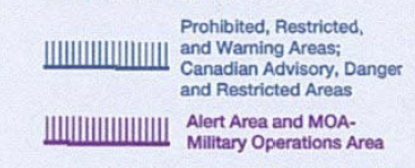
Special Use Airspace
Prohibited, restricted, and warning areas are shown with the blue special use airspace symbology. Military operations areas are shown with the same symbol in magenta. The Washington, DC flight restricted zone (FRZ) is depicted using the prohibited/restricted/warning area symbology.
Other Airspace Areas
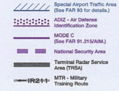
A thin, solid magenta line depicts the boundaries of Mode C required airspace. Mode C is required from the surface to 10,000 feet within 30 NM of the primary airport of a Class B airspace.
FAR Part 93 airports, where special air traffic rules and airport traffic patterns apply, are shown by "bosing" of the airport name.
A broken magenta line depicts national security areas. These special flight rules areas are established at locations where there is a requirement for increased security and safety of ground facilities. Pilots are requested to voluntarily avoid flying through these depicted areas. When necessary, flight through these areas may be temporarily prohibited.
A magenta symbol of dots over a solid line depicts the boundaries of the air defense identification zone, or ADIZ.
Terminal Radar Service Areas (TRSAs) are shown by a screened black outline of the entire area and various sectors within the area. Sector floor and ceiling altitudes are shown, with the last two digits omitted.
Military Training Routes (MTRs) are shown on sectional and terminal charts. An MTR designated with a name containing four numbers indicates that the entire MTR is at or below 1,500 feet AGL. If the MTR's name contains three or fewer numbers, than some segments of the MTR are above 1,500 feet AGL. "VR" or "IR" in the MTR's name indicates whether the route is flown visually or by reference to instruments. Route widths vary between four and 16 miles.
terminal chart coverage is shown with a 1/4 inch masked line. Inset coverage is depicted with a 1/8 inch masked line.