The Pilot Briefing
Below the top margin, the pilot briefing section of the chart provides the pilot information required to complete the approach. It lists the navaid used to provide approach guidance and its frequency, the final approach course, and runway information.
Below these items there is a notes section. This notes section must be read, as it might contain vital information. Additionally, the existence of nonstandard takeoff or alternate minimums is noted here. Nonstandard takeoff minimums are noted by a white T inside an upside down black triangle, while nonstandard alternate minimums are noted by a white A inside a black triangle. If the letters "NA" are present next to the nonstandard alternate minimums symbols, alternate minimums are not authorized for this airport.
After the notes, missed approach instructions are listed, followed by communications frequencies. Frequencies are listed in the order they would be used during the approach.
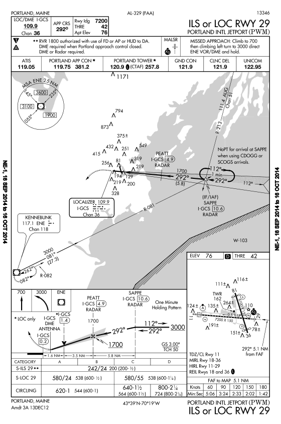
The Plan View
Below the pilot briefing section, we have the plan view. This is an overhead view designed to guide pilots from the enroute phase to the initial approach fix, or IAF.
The procedure track is depicted, along with obstacle elevations, reference navaids and fixes, and relevant airspace. Airports other than the primary approach chart airport are not normally depicted.
Terrain is depicted on the plan view if terrain within the plan view exceeds 4,000 feet above the airport elevation or 2,000 feet when within a 6 nm radius of the airport reference point.
Spot elevations are listed by a dot and an associated MSL altitude. Obstructions are shown with an inverted V with a dot and an MSL altitude. The highest spot elevation and highest obstruction is indicated with a larger, bolder version of the same symbol.
When appropriate navaids are available, an MSA will be listed. This minimum safe altitude is for emergency purposes, and provides 1,000 feet of obstruction clearance as depicted on the chart. The chart depicts the navaid used, the distance from that navaid for which the MSA applies, and the MSA altitude. The MSA radius is normally 25 nm. The MSA may be broken up into a number of sectors, when necessary. For example, the MSA may be listed as 2500 feet southeast of the reference point, but 2900 feet to the northwest.
The MSA is normally predicated on the navaid used for guidance on the instrument approach. For straight in RNAV approaches, MSA is normally predicated on the runway waypoint. For circling RNAV approaches, the airport waypoint is usually used. And, for GPS approaches, the missed approach waypoint is normally used.
The plan view may or may not be drawn to scale. The primary concern is given to aiding the pilot in understanding the procedure over accuracy of the scale. Some procedures contain a reference circle, normally drawn at a 10 mile radius. Only the information within the reference circle is drawn to scale.
If all information required for the procedure will not fit in the plan view in a clearly understandable way, the chart may contain concentric dashed circles. These circles are used to arrange information in its relative position outside the reference circle. This method often aids in the depiction of enroute and feeder facilities.
Navaids used for the procedure are shown, along with their names, frequencies, and Morse code identifiers.
A bold line is used to mark the main procedure track. A medium line is used for feeder routes, and a thin line is used to depict radials. The missed approach track is drawn as a thin, hash mark line with a directional arrow. A thick dashed line with a directional arrow is used where a visual flight path segment is charted.
A feeder route depicted in an approach chart is only navigable when heading, altitude, and distance information are designated for the route on the chart.