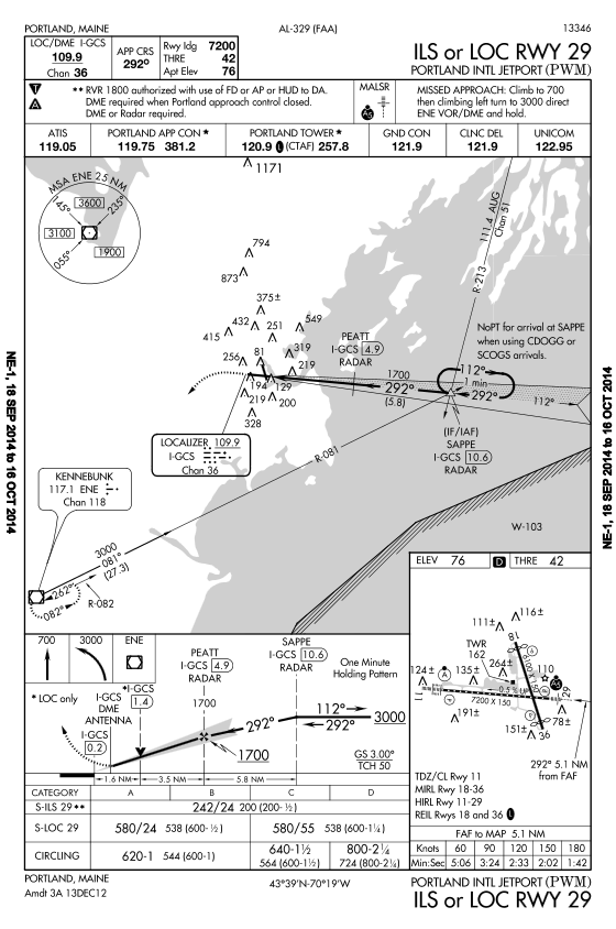
To the right of the notes, we are shown the "A5" symbol. This is the symbol used when the runway is equipped with a medium intensity approach lighting system, or MALSR. Notice the white lettering on a black background. This is actually the inversed version of the normal black lettering on a white background. The inversed version shown indicates that the MALSR system is pilot controlled. The missed approach instructions call for a climb to 700 feet, then a climbing left turn to 3,000 feet direct to Kennebunk VOR/DME to hold.
On the next line we are given pertinent communications frequencies, listed in the order we will use them. The asterisks indicate Portland approach and tower are part time. The tower frequency of 120.9 is used as a CTAF when the tower is closed. Pilot controlled lighting is also controlled on that frequency.
Next we take a look at the plan view. We see the minimum safe altitude is based off Kennebunk VOR/DME and is valid to a 25 nm radius. Three MSA sectors are depicted with altitudes of 3,600 MSL, 3,100 MSL, and 1,900 MSL.
A number of obstacles are shown in the plan view, the highest being up north being 1,171 MSL at the top. Notice the plus and minus symbol next to an obstacle with a top at 375 feet MSL. This symbol indicates that 375 foot elevation may not be accurate.
The thin line drawn from AUG indicates the 213 radial can be used to define the SAPPE intersection. Alternatively, we could identify it as the I-GCS 10.6 DME on the localizer. This course is not navigable because it does not depict an altitude, course, and distance. The radial from ENE does, however. This means the ENE 081 degree radial is usable as a route to SAPPE. This is also indicated by the use of a medium intensity line to depict the radial as a feeder route. The MEA along this route is 3,000 feet.
The note on the plan view states we are not to conduct a procedure turn at SAPPE if we arrive via the CDOGG or SCOGS standard arrival procedures. A warning area is depicted in the southeast corner of the plan view. It is designated W-103. Finally, notice that SAPPE is an initial approach fix, and also might be an intermediate approach fix, depending on whether we need to do a course reversal over SAPPE or not.
The profile view depicts much of the same information as the plan view. This information can sometimes be confusing to learn, since it contains information for two different approaches. This chart can be used with either the ILS or the LOC approach to runway 29. The final approach fix on an ILS is the point at which the glide slope is intercepted. The lightning bolt symbol shows the lowest possible glide slope intercept altitude and location. If we were shooting the localizer approach, the fix marked by the maltese cross symbol represents the final approach fix. In this case, they are the same.
To use the minimums section, we determine our approach category. Straight in minimums on the ILS are a decision altitude of 242 feet and visibility of 2400 RVR. Straight in minimums for the LOC approach are 580 feet and 2400 RVR or 5500 RVR if category C or D. Regardless of whether we are on the ILS or LOC approach, if we intend to land on a runway other than runway 29, we must circle to that runway. In that case, we would use circling instead of straight in minimums.
If RVR is not available for an IAP, but RVR visibility minimums are given, the pilot can convert the given RVR values to their equivalent values in statute miles. This is accomplished by memorizing the conversion or looking it up on a conversion table.
The RVR to statute mile conversion table is available to you during your knowledge test. See legend 11.